
Start
3. 1. 2023
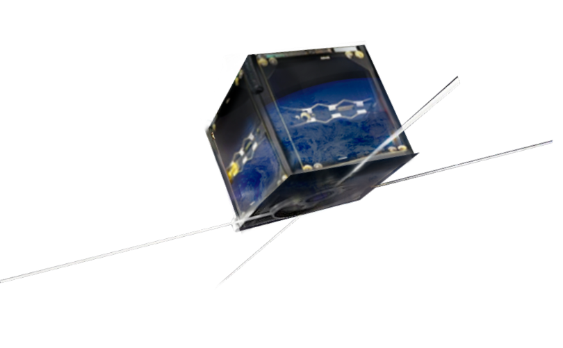
3.1.2023 v odpoledních hodinách byl na oběžnou dráhu vynesen cubesat BDSAT-2, a to raketou Falcon 9 společnosti SpaceX.


ZOBRAZIT VÍCE
BDSAT je nanosatelit, tzv Cubesat, o velikosti 10x10x10 cm. Kosmická technologie nanosatelitů představuje velký technologický trend. I přes své malé rozměry a hmotnost začínají Cubesaty přebírat některé úlohy větších satelitů, neboť představují nízkonákladovou variantu pro vývoj a testování nových technologií v kosmu.
ZOBRAZIT VÍCE
Byla zahájena první měření a také experimenty na tzv. payloadu, což jsou tlakoměry a banka superkapacitorů BD SENSORS, které cubesat BDSAT-2 nese! Zde si můžete zobrazit aktuálně přijatá data z BDSAT-2!
3.1.2023 v odpoledních hodinách byl na oběžnou dráhu vynesen cubesat BDSAT-2, a to raketou Falcon 9 společnosti SpaceX.
ZOBRAZIT VÍCE
Společnosti BD SENSORS se důslednou strategií výroby a kvality v průběhu několika málo let podařilo dosáhnout postavení významného producenta elektronické tlakoměrné techniky v celosvětovém měřítku.
ZOBRAZIT VÍCE
ZOBRAZIT VÍCE
Náš satelit BDSAT byl na oběžnou dráhu vynesen raketou Falcon 9 společnosti SpaceX, a to spolu s několika dalšími cubesaty. Vše proběhlo v pořádku a nyní jsou již přijímána telemetrická data!
Projekt BDSAT má za cíl podpořit radioamatérskou komunitu několika HAM službami a aktivitami. Sekundárním cílem je ověření prototypu tlakoměrného zařízení a ověření funkčnosti této technologie v podmínkách otevřeného vesmíru. Bude ověřena funkce samotného měření, jeho proveditelnost a vhodnost pro použití v družicích v kosmických podmínkách. Druhou částí technologického experimentu je ověření využití superkapacitorů jako moderního řešení pro ukládání energie v družicích.
ZOBRAZIT VÍCE
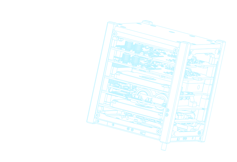
Projekt BDSAT je rozdělen do dvou částí. V prvé řadě bude testovat tlakové senzory BD SENSORS v podmínkách otevřeného kosmu. Tyto senzory musí splňovat velmi náročné požadavky jak z hlediska přežití v drsných podmínkách vesmíru, tak z hlediska zachování přesnosti a ostatních technických parametrů. Spolehlivost technologií je pro budoucí kosmické aplikace naprosto zásadní.
Součástí experimentu je také ověření funkce banky superkapacitorů. Jedná se o výkonný zdroj pro ukládání elektrické energie pro systémy družic. V budoucnu může banka superkapacitorů nahradit konvenční bateriové napájecí systémy. Soustava bude během letové fáze přivrácené ke Slunci nabíjená energií ze solárních panelů. Během druhé fáze letu bez dodávky energie ze solárních panelů se energie z tohoto zdroje bude vybíjet do umělé zátěže.
ZOBRAZIT VÍCE